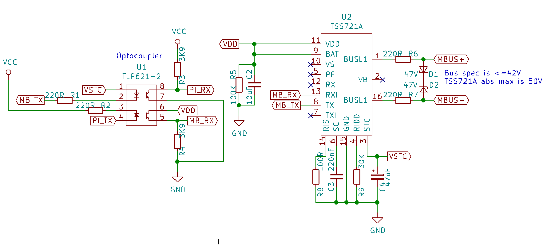
M-Bus Slave Device Schematic
One of my earliest reasons for dabbling with IOT devices was to be able to remote read the heat meter on my wood fired central heating. That heat meter uses the M-Bus protocol to expose meter information, and it’s much more useful to access that it might first appear - the meter doesn’t just provide a real-time reading of the amount of heat generated by the installation since the beginning of time, but also
- current instantaneous heat output
- current flow and return temperatures
- current flow rate
- various alarm info.
I’ve coupled these readings with other readings from elsewhere in my heating installation to get a pretty comprehensive view of what’s happening at any point in time, which in turn has helped me improve the overall system efficiency.
I’ve already built some M-Bus support into otb-iob but given a recent enquiry wondered what it would take to build an M-Bus master on a Raspberry Pi. The cost would be higher than an ESP8266 (because the Pis aren’t that cheap), but the ease of use could be much higher, as it would be relatively straighforward to build a RESTful HTTP API on top of the pi given existing tools.
To enable testing of that project without needing to use my heat meter as a test device, I’ve also designed an M-Bus slave to run on top of a Pi. I thought the schematic for the slave might be useful to someone out there - although it’s a pretty straightfoward device to build leveraging the TI TSS721A and an opto-coupler for galvanic isolation.

Two notes:
- This is untested - I’m still waiting for the prototype PCBs implementing this to arrive.
- It’s not an M-Bus master design. You can find one of those here.