MCP 24AA00 Family of I2C EEPROM chips
MCP 24AA00 Family of I2C EEPROM chips
I want to be able to burn my own serial numbers and other “factory” information into my designs. Even though the ESP8266 is deployed with flash memory, this is used for firmware and run-time configuration, with the chip itself having the MAC address burnt in at the factory. I want something similar, which users can’t (it find harder) to change.
In searching I came across the Microchip Serial EEPROM range. This comes with support for a variety of protocols, of which most interest to me at the moment is I2C.
Variants
The Microchip range of I2C eeproms are named according to the following rules - 24XXYY where:
-
XX = voltage/temperature range (AA, LC, C)
-
YY = capacity
The voltage and temperature ranges I’ve found are:
-
XX = AA, 1.8 <= Vcc <= 5.5, -40C <= temp <= +85C
-
XX = LC, 2.5 <= Vcc <= 5.5, -40C <= temp <= +85C
-
XX = C, 4.5 <= Vcc <= 5.5, -40C <= temp <= +125C
And the capacities are:
-
YY = 00, 128 bit (16 bytes)
-
YY = 01, 1 Kbit (128 bytes)
-
YY = 02, 2 Kbit (256 bytes)
-
YY = 04, 4 Kbit (512 bytes)
-
YY = 08, 8 Kbit (1KB)
-
YY = 16, 16 Kbit (2KB)
-
YY = 32, 32 Kbit (4KB)
-
YY = 64, 64 Kbit (8KB)
-
YY = 128, 128 Kbit (16KB)
-
YY = 256, 256 Kbit (32KB)
-
YY = 512, 512 Kbit (64KB)
-
YY = 1024, 1024 Kbit (128KB)
So the 24AA00 is a 128-bit device, tolerant of 1.8V - 5.5V - and is the one I’ve been experimenting with.
Where the voltage/temperature are not important XX is typically used - so the datasheet for the 24AA00 talks about 24XX00.
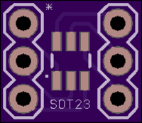
These devicea are available in the usual range of PDIP, SOIC, TSSOP, SOT-23 and DFN/QFN packages. I used the SOT-23 (hence my breakout board):
Controlling the device
The 24XX00 is the simplest of the range, and is controlled as follows:
-
It supports a single (non configurable) I2C address - 0x50 - although the 3 least significant bits are ignored.
-
A byte is written by:
-
Signaling the device on the I2C bus using the address followed by the wite bit (0) - the device will ack.
-
Signaling the word (byte) address to be written (where the 4 most significant bits are ignored, as this device only supports 16 bytes of data) - the device will ack.
-
Writing the byte of data to stored - again the device will ack, but this does not mean the data is written yet.
-
Sending a stop - the device will now write the byte and not respond to any further messages until this is done. The datasheet recommends polling (via an attempt to write the word address) - when an ack is received, the byte has been stored.
-
The 24XX00 does not support sequential writing - each one must be addressed and written (and polled for an ack) in turn.
-
Reading is just as simple, and the device does support sequential reading:
-
Write the word address to be read.
-
Now indicate a read to the device.
-
Read a byte.
-
If the master acks the device will send the next byte (and if address 0xf was the last to be read it will cycle back to 0).
-
If the master doesn’t ack the device won’t send any further bytes.
The 24XX00 was pretty easy to get working, and claims to support up to 1M erase/write cycles. I found with the ESP8266 it took 18 iterations round a tight polling loop for the device to ack the write.
If you’d like to take a look at a prototype 24XX00 implementation for the ESP8266, see the otb-iot source.
Higher Capacity EEPROMs
The 24XX00 is probably not the device I’ll end up using as:
-
it doesn’t have enough capacity (I’m probably going to be looking at around 16kbit so I can at least store a 4096 RSA key signature)
-
it doesn’t have any facility to write erase the contents - so any other master on the I2C bus could rewrite the contents (either by accident or maliciously) - and I don’t want to have to have multiple I2C buses.
The larger devices are a bit more interesting with a number of extra capabilities:
-
More capacity!
-
Sequential writes - between 8 and 16 bytes can typically be written at a time, and stored in a buffer on the device, before it actually stores them.
-
Write protect capability - typically either the entire array, or the top half can be protected by pulling a pin up to Vcc.
ESP32
I’m interested that the ESP32 has some OTP (one time programmable) memory, with 768-bits available for device manufacturers. Sadly this probably won’t be enough for my needs.
comments powered by Disqus