First Own ESP8266 Module Design
First Own ESP8266 Module Design
I recently spent an entertaining couple of days on holiday designing my own ESP8266 module.
There’s tons of different modules already available, but I specifically want one which
-
supports an external attenna
-
has 4MB (or greater) flash.
When I started designing my own module, the only commercially available one I was aware of which fitted the bill was the ESP-07E. However, this comes with a 1MB flash, which isn’t enough for me. I’ve a number of these 07Es, and have peeled off the PCB shield, and replaced the 1MB flash with 4MB. However, if I’m doing this I might as well have my own module, designed to my specifications :-).
Another disadvantage of the ESP-07E is the external uFL antenna port requires a cable and then antenna on the end of it - whereas I want a PCB mounted SMA port to keep price and complexity down. And finally, it’s an opportunity to look into RF PCB design, and also play around with 0402 SMD components (I’ve only gone down to 0603 previously).
Of course, since I’ve designed this board, I’ve now seen reference to both the ESP-07S and ESP-100 (and have some ESP-07S on order). These have larger 4MB and 8MB flash respectively. At least it was a useful learning opportunity!
I started off by looking at Espressif’s ESP8266 reference design (in the form of the ESP-WROOM module, for which they provide schematics, and the ESP8266 datasheet and other docs which give useful information about the recommended PCB design criteria.
I found during this research that RF designs usually use a minimum of 4 layer boards. I’m a cheap-skate and only want to use 2 layer boards, so accept my design will be sub-optimal - and probably in more ways than one!
Particular challenges that stick in my mind (but not a comprehensive list):
-
0402 components are recommended on the RF antenna trace to reduce inductance
-
keep a ground plane under all RF traces
-
keep other traces as far away as possible from the RF trace
-
minimize vias on all RF, oscillator and high speed data (SPI) lines
-
try and keep all SPI lines the same length (yeah, right!)
-
whereas most ESP modules use a 26kHz oscillator for clocking, a 40kHZ oscillator should ensure that the UART output from the chip will come out by default at 115200kbps instead of the rather odd 74880 with the 26kHz oscillator - which is a nice optimization
-
as for RF traces, oscillator traces and components should generally be kept away from other traces
-
worth using an EMI shield on the module, to reduce noise output (and as I can’t find sensibly sized, sensibly priced ones, I’m going to try and build my own - more on this experiment some other time!)
-
I want to use castellations to connect this module to my other boards, so needed to follow OSHPark’s guidelines on how to achieve this
-
produce something as small as possible to keep price and footprint low.
(I’ve since found this article on general RF and mixed-signal PCBs which seems very useful!)
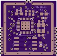
I’m quite pleased with what I’ve ended up with:
It’s 20mm x 20mm and cost me $3.10 for three. I haven’t figured out the entire BOM cost yet (but you can be sure it’ll be more than the mass-produced ones). However at even small volumes price comes down massively - if I used Dirty PCBs 10x10 service and panelized them 4x4 I’d get them at under $0.16 each.
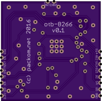
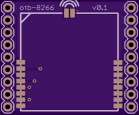
As an added bonus those fabulous folks from OSHPark upgraded me to super swift service for this board, and the corresponding breakout I have on its way - with both shipping pretty much exactly 1 week after ordering. The breakout board is shown below.
As these haven’t arrived yet I don’t know how successful they’ll be, or how easy I’ll find dealing with the 0402s - but not having had any problems with 0603s or various QFN packages, I’m not expecting too much trouble.
Am happy to post the Eagle schematic and board layout files if anyone asks for them. Sorry, no KiCad - I started out designing PCBs with Eagle and haven’t yet summoned up the energy to learn another platform (especially now I feel like I’ve really got to grips with Eagle!)
The breakout board for the above module is here:

Edit 29 March 2018
The Eagle .brd and .sch files for the esp8266 and esp8266 breakout designs can be found here.
comments powered by Disqus