ESPi - The ESP8266 masquerading as a Raspberry Pi Zero
While recently developing Raspberry Pi Hats - which are mezzanine boards that plug into a Raspberry Pi to provide additional functionality - it occurred to me that it would be a much more cost effective solution if these hats could be driven by an ESP8266. The hats I’ve developed are quite low in terms of their demand on computing power, but do need network connectivity, and hence the ESP8266 is well suited to driving them.
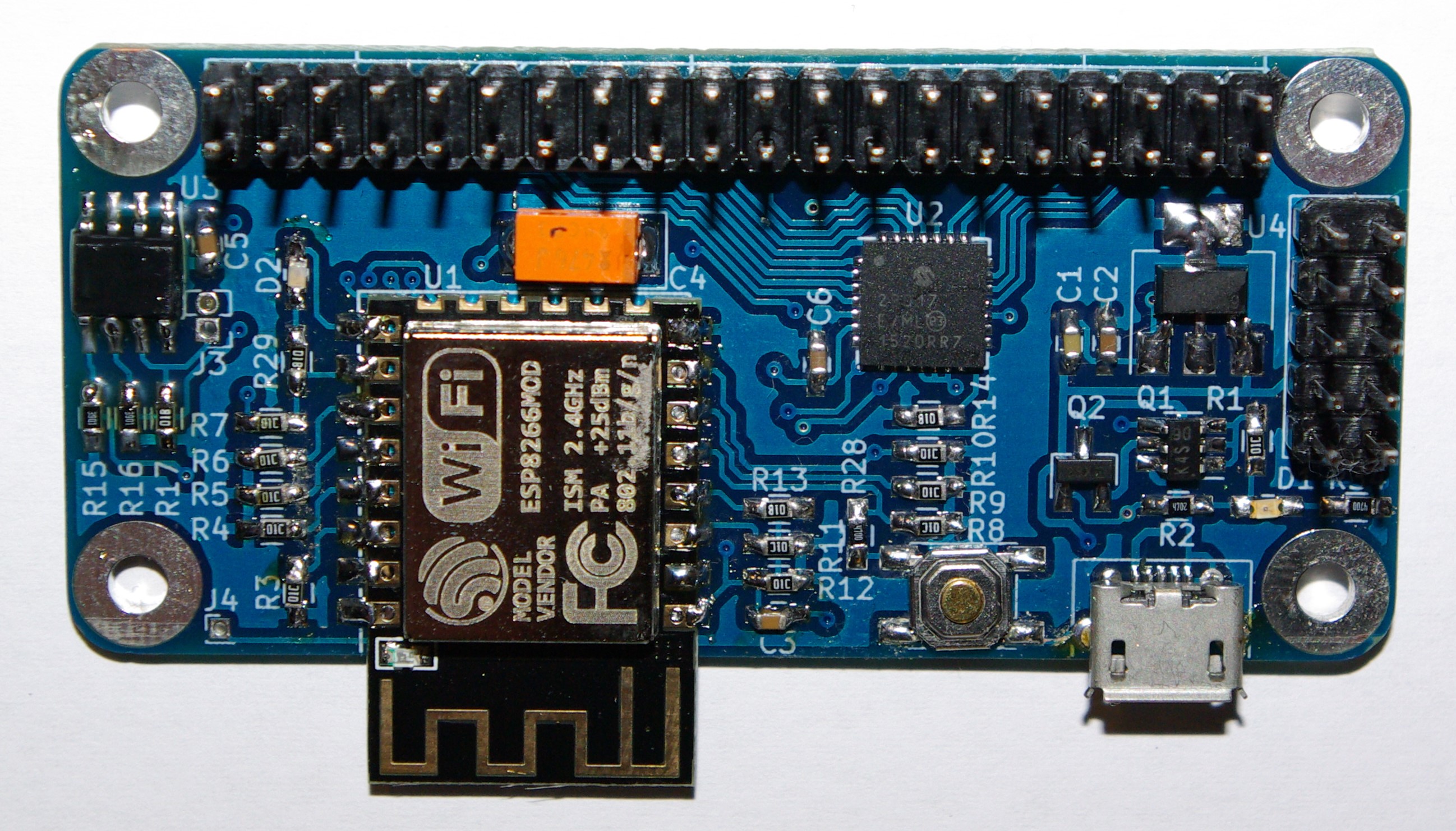
So, I’ve developed what I’m calling the ESPi (pronounced E-S-Pi):
It’s key features are:
- It uses the Raspberry Pi Zero form factor.
- It has the same main 40 way pin header, in the same location.
- It has the same pinout, meaning the same power pins in the same locations, and supports GPIOs on the other pins.
- The power jack is in the same location as the Pi Zero.
- The power LED is pretty much in the same location as the Pi Zero.
- It also has an additional LED attached to the ESP8266’s GPIO 15, which can be used for status reporting.
- It supports ESP-12 and ESP-07 ESP8266 sub-boards (which is essentially the cheapest way to source the ESP8266 and supporting componentry).
- It features an onboard 24LC series eeprom at address 0x57, so as not to clash with the Pi Hat’s eeprom. This can be used by applications to store additional configuration or programming data.
- It can be safely back powered by a Hat, as can the Raspberry Pi.
- otb-iot supports it :-).
I had to make some compromises in squeezing this all in to a pi-zero form factor, but this was important to me as
- I wanted to keep cost as low as possible
- I’m generally aiming to develop Pi Zero hats, so the form factor is more applicable
- I like the challenge of laying out in as small space as possible.
The key compromises I made here were:
-
The wifi antenna of the ESP-12 extends over the edge of the board. This is important if you have ground/power planes on your PCB (the ESPi does) to ensure the best reception, and it’s sticking out roughly where the mini-HDMI jack is on the Pi Zero, but the ESP sub-board is wider - so could be an issue in some implementations. I wanted to extend it out over the left hand side (where the camera connector is on a zero), but the space between the mounting posts is just too small. Another approach would be to use an ESP-07 sub-board (instead of the ESP-12), which doesn’t include an antenna and hence doesn’t stick out - but does need an external antenna.
-
To get enough usable GPIOs I needed to use a GPIO expander IC. I went with the MCP23017, an I2C controlled IC. This in itself wasn’t a compromise but using the QFN package was - this is a pain to hand solder compared with the SOIC or TSSOP packages. But for someone who watches Louis Rossmann regularly isn’t too much of a challenge!
-
I really, really wanted a hard reset button on the board (pulling RST/GPIO16 low), as resetting the ESP8266 by unplugging and replugging is tedious. But I just couldn’t fit it in, and opted to include a soft reset button instead (which pulls GPIO14 low - and which can be detected in software).
-
I have some pads on the underneath to modify the ESP8266 (and MCP23017) to Pi form factor GPIO mappings. I went with 0201 pads (!) in the hope I could jumper these with solder bridges. Turns out I can’t so I need to jumper with small wires. Again a faff.
-
Not putting anything on the underside. Green lighting the underside would have given me much more room to work with, but as the Pi Zero has no components on the bottom, I wanted to keep this the same.
-
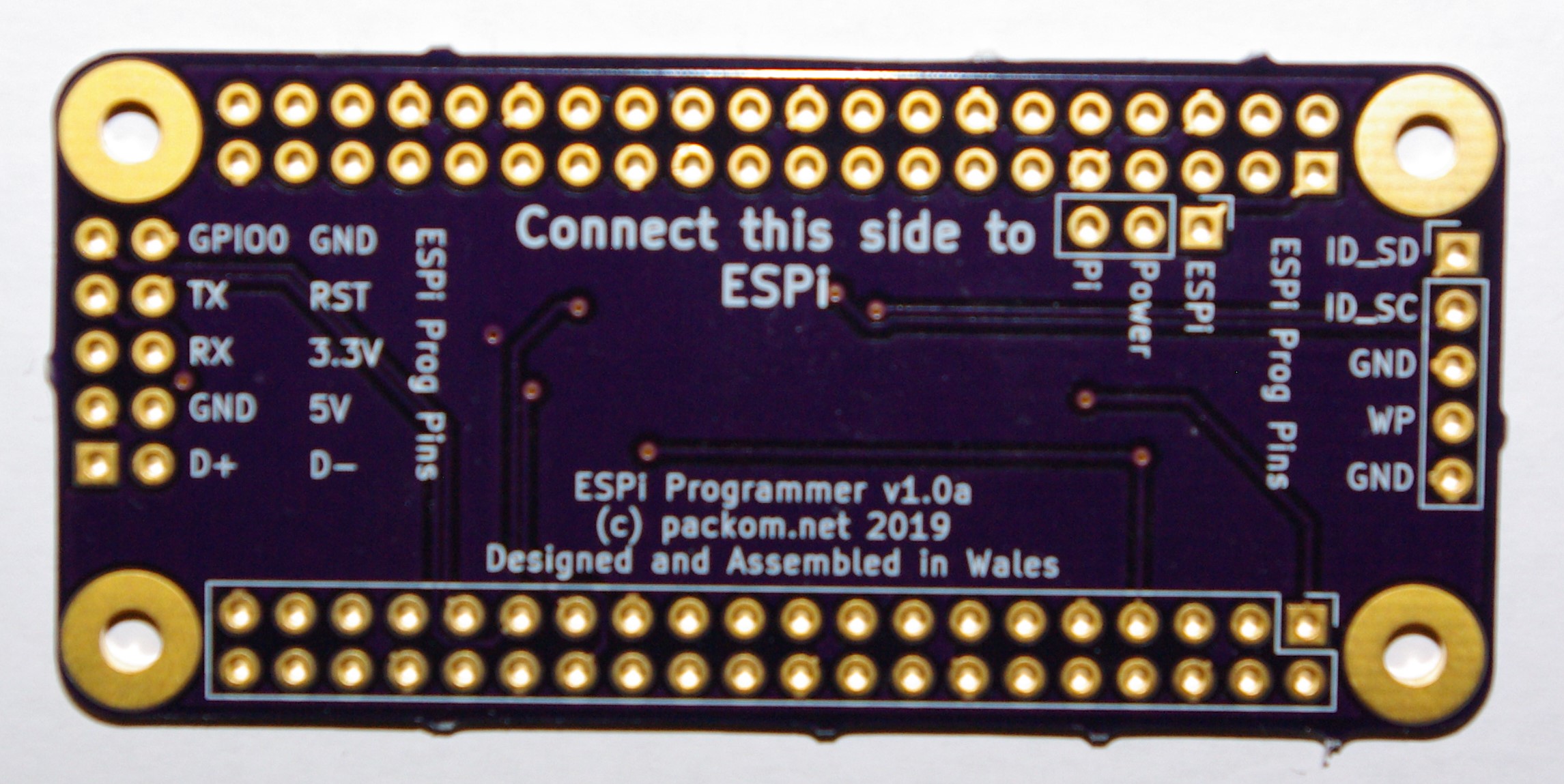
I’ve put an extra pin header on the ESPi, to allow easy programming. However, this means its incompatible with any Raspberry Pi Hat which expects to mate with a PoE connector.
I have a few ideas for improvements to the layout for the new revision, which should allow me to squeeze the hard reset button in.
In fact though, this turns out not to be a problem, as I have also developed an ESPi programming board which allows the ESPi to plug directly into a Raspberry Pi so the Pi can program it. It is itself a Pi Hat, and it detected as such by the pay. In this state the Pi can also hard reset the ESPi, overcoming the lack of hard reset button on the ESPi.
The main purpose of developing the ESPi is as an experiment and for personal use. If there’s any interest I may be prepared to sell pre-assembled ESPi boards, and/or release the schematic and KiCad files. If you’re interested in either of these post below in comments, or contact me.
comments powered by Disqus